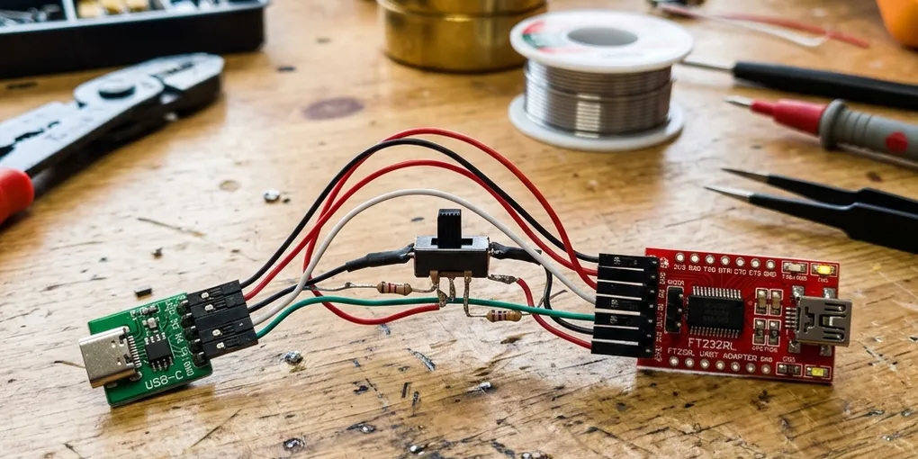
Building a DIY PineTab2 UART debug adapter with Maskrom switch
The PineTab2 ships with a clever little USB-C UART dongle that does two things at once: it gives you a serial console over the tablet’s SBU pins, and it has a switch that puts the SoC into Maskrom mode for recovery. Mine has been bouncing around in a drawer with the charging cable, and after misplacing it for the third time I decided to build a spare from parts I already had on the bench. Here’s the full recipe.
This build assumes you’ve never soldered to a USB-C breakout before. If you’ve done a few, skip straight to the wiring table.
What you’re building
A wired-together version of the official Pine64 dongle. It plugs into the PineTab2’s far USB-C port and exposes a TTL serial console to your computer at 1.5 Mbps, plus a switch that disables eMMC/SPI boot so you can either boot from microSD or drop into Rockchip Maskrom mode for rkdeveloptool recovery.
The official dongle uses a CH340N USB-to-serial chip with a passthrough OTG port. This build uses a pre-assembled FTDI adapter instead, which keeps the soldering down to the USB-C breakout and the switch — no SMD work required.
How the design works
The PineTab2’s far USB-C port is non-standard. It carries USB OTG on the normal D+/D- pins, but it also repurposes other pins to detect a UART dongle and read a Maskrom strap:
- The tablet sees both
CC1andCC2pulled to GND through 5.1 kΩ resistors and recognises a USB-C Debug Accessory. - UART TX and RX ride on the
SBU1andSBU2pins at 3.3V logic level. - The
A6pin (which on a normal USB-C cable would be the primary-orientation D+) is repurposed as the eMMC/SPI disable strap. Pulled high through 10 kΩ during boot = normal. Shorted to GND during boot = skip eMMC and SPI, fall back to SD or Maskrom.
The Pine64 dongle’s schematic is published at pine64.org — if you want to verify any of this yourself, look for the file labelled PineTab2/PineTab-V UART Dongle Schematic-20221107.
Parts list
| Part | Notes |
|---|---|
| DSD Tech SH-U09C | FTDI FT232RL USB-to-TTL adapter. Set the voltage jumper to 3.3V. |
| flashtree USB-C 24-pin male breakout | Any 24-pin USB-C breakout works; flashtree’s is well-labelled. Use the male version so it plugs directly into the tablet. |
| 2× 5.1 kΩ resistors | CC pull-downs for Debug Accessory Mode. 1/8 W, any tolerance is fine. |
| 1× 10 kΩ resistor | Pull-up on the Maskrom strap. |
| 2× 22 Ω resistors (optional) | Series termination on the SBU lines. 33 Ω works equally well, and you can skip these entirely without affecting operation at 1.5 Mbps. |
| 1× small slide switch (SPDT) | Three terminals. Any panel-mount or PCB slide switch with reasonable lead spacing for hand soldering. |
| Thin solid-core wire | 28–30 AWG works well for the USB-C breakout pads. |
| Heat shrink or kapton tape | To insulate everything once it works. |
You could substitute a CP2102N-based adapter (DSD Tech SH-U09B2) — it’s also great, but the 3.3V rail isn’t exposed on the header. The SH-U09C’s exposed 3.3V pin makes wiring the pull-up trivial.
Why these resistor values
If you’ve read the schematic you’ll notice it shows 24 Ω on the SBU lines. 22 Ω or 33 Ω both work just as well — these are series termination resistors for signal damping, and at 1.5 Mbps over a few centimetres of hookup wire the exact value doesn’t matter. 22 Ω is closer to the original and what I’d default to; 33 Ω is what you probably already have from a USB high-speed bin. You can also skip them entirely and use a direct wire.
The 5.1 kΩ CC pull-downs are not optional — they’re what tells the tablet you’ve plugged in a debug accessory. The USB-C spec is strict about this value. Don’t substitute 10 kΩ or 4.7 kΩ “because that’s what I had”; get the 5.1 kΩ.
Wiring
Here’s the full pinout. Refer to your breakout’s silkscreen — flashtree labels every pin, but verify with a multimeter against the USB-C pinout reference before soldering.
| Wire | From breakout | To | In line |
|---|---|---|---|
| 1 | A5 (CC1) | GND | 5.1 kΩ |
| 2 | B5 (CC2) | GND | 5.1 kΩ |
| 3 | A8 (SBU1) | SH-U09C RXD | optional 22 Ω |
| 4 | B8 (SBU2) | SH-U09C TXD | optional 22 Ω |
| 5 | A1 or A12 (GND) | SH-U09C GND | none |
| 6 | A6 (D+1) | Switch pole (center) | none |
| 7 | Switch OFF terminal | SH-U09C 3.3V | 10 kΩ |
| 8 | Switch ON terminal | GND | none |
The Maskrom switch’s “OFF” position connects A6 to 3.3V through the 10 kΩ resistor — normal boot. The “ON” position shorts A6 directly to GND — disables eMMC/SPI.
Soldering, step by step
The USB-C breakout pads are tiny. A fine-tip iron (1 mm conical or smaller), 350 °C / 660 °F, and thin solder (0.5 mm rosin-core) will save you a lot of frustration.
-
Plan your wire routing first. Lay the breakout and the SH-U09C side by side on your bench in the orientation you want them in the final build. Decide which side the switch sits on. Pre-cut your jumper wires to length — 2–3 cm is plenty.
-
Tin every pad you’ll use. Touch the iron to each target pad for half a second, then feed a tiny dot of solder. You want a small dome, not a flood. The pads you need: A5, B5, A8, B8, A6, A1, A12. Be especially careful around A5 (next to A4/VBUS — a bridge there is bad) and A6 (next to A7).
-
Strip and tin your wire tips. Strip about 1 mm — any more and you risk shorts to adjacent pads. Twist the strands if it’s stranded, then tin each tip.
-
Solder the CC pull-downs first. These are the trickiest because A5 sits adjacent to VBUS. Solder one leg of a 5.1 kΩ resistor to A5 and the other to any GND pad (A1 or A12 are both convenient). Repeat with B5. After both, check with a multimeter: A5→GND should read 5.1 kΩ, B5→GND should read 5.1 kΩ, and A5→A4 (VBUS) should read open (no continuity).
-
Solder the UART lines. Wire A8 to the SH-U09C’s RXD pin, B8 to TXD. If you’re using the 22 Ω series resistors, splice them in line by trimming the wire in the middle, stripping both ends, and soldering the resistor between. Heat-shrink each splice.
-
Solder a ground wire. A1 or A12 on the breakout to the SH-U09C’s GND pin.
-
Test the console before adding the switch. Plug the breakout into the PineTab2’s far USB-C port (face up — the LED on the SH-U09C should be the only thing lit when you first plug in). Plug the SH-U09C into your computer via USB-A. Run
sudo dmesg --followand look for theftdi_siodriver attaching and creating/dev/ttyUSB0. Then:sudo screen /dev/ttyUSB0 1500000Power on the PineTab2. You should see U-Boot output stream past. If you don’t, flip the breakout 180° (orientation determines which SBU pin connects to TX vs RX). If you see garbage, double-check you set the SH-U09C’s voltage jumper to 3.3V.
-
Once console works, add the Maskrom switch. Solder a wire from A6 to the switch’s center pole. Solder one outer terminal to GND. Solder the other outer terminal through a 10 kΩ resistor to the SH-U09C’s 3.3V VCC pin (pop the clear case off the SH-U09C — the 3.3V pin is labelled on the PCB next to the header).
-
Verify the switch with a multimeter.
- Switch in OFF position, SH-U09C plugged in: A6 reads ~3.3V relative to GND.
- Switch in ON position: A6 reads ~0V (shorted to GND).
-
Heat-shrink everything. Wrap exposed solder joints and bare resistor leads. The goal is no possible shorts between adjacent USB-C pins once the breakout is plugged in.
Testing Maskrom mode
With the build complete:
- Power off the PineTab2 by holding the power button for 5 seconds.
- Flip the Maskrom switch to ON.
- Plug the dongle into the far USB-C port.
- Plug a separate USB-C-to-USB-A cable from the other USB-C port (the one closer to the power button) to your computer. This is the OTG path that
rkdeveloptoolwill talk to. - Hold the power button to turn the tablet on.
- On your computer, run
lsusb. You should seeFuzhou Rockchip Electronics Company Device— that’s the Rockchip Maskrom downloader. If you seeQinHeng Electronics USB Serialonly, the OTG cable isn’t seated or you’ve got the ports swapped.
You can then use rkdeveloptool to flash a recovery image, push a miniloader, or do whatever recovery you needed Maskrom mode for in the first place. Just remember to flip the switch back to OFF before normal use, or the tablet will skip eMMC every boot.
Caveats and gotchas
-
The switch position is only read at power-on. Flipping it while the tablet is running does nothing. Power down, flip, power up.
-
brlttywill fight you on Ubuntu. If you seeinterface 0 claimed by ftdi_sio while 'brltty' sets config #1indmesg, either removebrltty(sudo apt remove brltty) or unbind it from the FT232’s USB ID. This isn’t unique to this build — it’s a long-running annoyance for anyone doing serial work on Ubuntu. -
No passthrough power delivery. The official dongle has a second USB-C female port for charging the tablet while debugging. This build skips that — if you need to charge while debugging, use the tablet’s other USB-C port. (You can’t pass PD through a 24-pin breakout without significantly more circuitry, so it’s not worth attempting.)
-
No USB OTG passthrough on this dongle. For Maskrom mode you’ll use the tablet’s other USB-C port for the OTG connection, which works fine but means two cables instead of one.
-
You can’t toggle the Maskrom switch mid-boot. It’s a hardware strap, not a software signal.
What it cost me
Roughly $15 in parts if you don’t already have any of it on hand, less if you do. The official dongle is $10 from the Pine Store and is the right choice if you just want one that works. Building your own is worth it if you’ve already got the bin parts, want to understand the design, or want to spec a beefier USB-to-serial chip than the CH340N.
What I’d change next time
The next iteration of this for me will be a small PCB that mounts the SH-U09C-equivalent CP2102N chip directly alongside the USB-C male connector, with the switch on-board and a second USB-C female for PD passthrough. The hand-wired version works fine for debugging, but it’s not pretty and the wires get caught on everything. If I get around to designing that PCB, I’ll write it up here.
If you build one of these and hit a snag, the wiring table and multimeter checkpoints above should isolate the failure to a specific step. The most common mistakes I’ve seen are: TX/RX reversed (just flip the breakout 180°), CC pull-downs shorted to VBUS (re-solder A5 and B5), and the SH-U09C jumper left on 5V (move it to 3.3V).