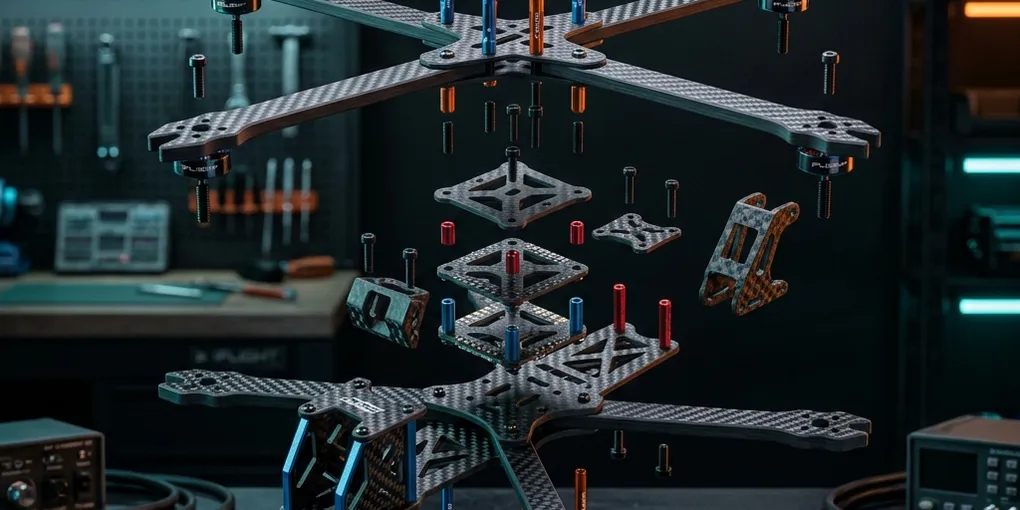
iFlight Chimera7 Pro V2 O4 (7.5" LR) — Complete Build Guide
This guide walks through building a complete 7.5” long-range FPV (First-Person View — you fly wearing goggles that show a live video feed from a camera on the drone) drone on the iFlight Chimera7 Pro V2 O4 frame, using a specific, verified BOM (Bill of Materials — the full parts list for the build). It’s written to be followed live, bench-side, by someone who has never built a drone: every term is defined the first time it appears, every stage opens with exactly the parts that stage uses, and nothing is left implied.
An earlier version of this post covered only the frame assembly. This revision expands it into the full build — electronics, soldering, wiring, software configuration, and first flight — and reorganizes the frame steps into the order you’d actually build in (you can’t wire electronics with the top plate already on, for example).
Downloads
- Complete Build Guide (PDF) — this full guide, formatted for printing
- Chimera7 Pro V2 User Manual (PDF) — iFlight’s official manual
- Screw Size Gauge (PDF) — print at 100% scale and lay screws over it to identify them by size
- RP4TD Receiver Manual (PDF) — RadioMaster’s official manual, mirrored (also on the product page)
A note on sources and certainty. Frame part names and item numbers come from iFlight’s official exploded-view parts list (“LR18005-Chimera7 Pro V2 O4 Frame Assembly Guide-250224.pdf”) — those are authoritative. Camera-stack installation details are corroborated by iFlight’s official O3→O4 upgrade video (youtube.com/watch?v=rWMadgjd4ic). Wiring pinouts come from this build’s BOM document and Holybro’s official Kakute H7 V2 pinout. The build order and any description of how parts physically stack are my interpretation of an isometric drawing — where stacking order or a fastener’s exact location matters, trust the numbered callouts in iFlight’s diagram over my prose, and dry-fit before you torque anything down.
The build at a glance
- Stage 1 — Bench-test every component (optional, but strongly recommended)
- Stage 2 — Solder the flight-controller/ESC stack, off-frame
- Stage 3 — Frame: bottom plate, arms, and standoffs
- Stage 4 — Mount and solder the motors
- Stage 5 — Mount the stack in the frame
- Stage 6 — Video system: camera stack and air unit wiring
- Stage 7 — Wire the receiver and GPS
- Stage 8 — Mount antennas, GPS, receiver, and buzzer
- Stage 9 — Top plate and battery hardware
- Stage 10 — Full bench test
- Stage 11 — Betaflight configuration
- Stage 12 — Props on and first flights
Complete parts list (BOM)
This build’s electronics were chosen and compatibility-verified as a set. The flight controller and ESC are bought together as the Holybro Kakute H7 V2 & Tekko32 F4 4-in-1 50A ESC Stack — a matched pair that shares mounting holes and connects with one included cable.
| # | Item | Qty | Notes |
|---|---|---|---|
| 1 | Frame — iFlight Chimera7 Pro V2 O4 Frame Kit | 1 | ~$110. Includes all screws, standoffs, TPU pieces, antenna pigtails, camera coax cable, battery straps (full hardware reference below) |
| 2 | Motors — iFlight XING 2806.5 1300KV (B007100) | 4 | 19×19mm M3 mount pattern — matches the frame’s arm tips |
| 3 | Flight controller (FC) — Holybro Kakute H7 V2 | 1 | Part of the Holybro stack — official docs · pinout |
| 4 | ESC — Holybro Tekko32 F4 4-in-1 50A | 1 | Part of the Holybro stack; ships with the 8-pin FC cable and a filter capacitor — official manuals |
| 5 | GPS — HGLRC Mini M100 | 1 | |
| 6 | Video — DJI O4 Air Unit Pro | 1 | ~$229; pairs with DJI Goggles N3 |
| 7 | Receiver (RX) — RadioMaster RP4TD ExpressLRS 2.4GHz | 1 | True-diversity (two antennas) — product & manual page |
| 8 | Props — HQProp 7×3.5×3 V1S, 3-blade | 8 (2 sets) | 5mm bore, secured by the motors’ M5 prop nuts |
| 9 | Battery — Ovonic 6S 3500mAh 130C, XT60 | 2 | |
| 10 | Buzzer — VIFLY Finder 2 | 1 | Self-contained lost-model beeper |
| 11 | Battery pigtail — XT60 male pigtail, 10cm 14AWG silicone wire | 1 (from a 5-pack) | Amazon B09M6KQWBL — soldered to the ESC in Stage 2 |
| 12 | Smoke stopper — ShortSaver V2 (XT30/XT60) | 1 | Amazon B088TVVNVM — an electronic fuse used at every first power-up |
Supporting gear (not consumed by the build): RadioMaster Boxer radio (ExpressLRS 2.4GHz), DJI Goggles N3, a 6S-capable LiPo balance charger.
Do not substitute parts and assume the wiring below still applies. The pinouts, UART assignments, and mounting patterns in this guide are specific to this exact BOM.
Tools & consumables
Soldering iron (TS101/Pinecil-class), 60/40 leaded solder, flux, isopropyl alcohol and a brush for cleanup, a multimeter, heat-shrink tubing, flush cutters, small hex drivers (1.5mm and 2mm for the frame; a full M2/M2.5/M3 set is much nicer than the single Allen key in the kit), tweezers for the small M1.6/M2 hardware, small (3mm) zip ties, Velcro strips, alligator-clip test leads, a USB-C data cable, and optionally thin CA glue or threadlocker for standoffs and motor screws.
Software (all free)
| Software | Purpose |
|---|---|
| Betaflight App (formerly Betaflight Configurator) | Configuring and flashing the flight controller. Now a web app (PWA) — needs a Chromium browser (Chrome/Edge); also a native Android app. Legacy desktop builds live on the same releases page |
| ExpressLRS Configurator | Flashing the radio link firmware (TX module and receiver) |
| DJI Assistant 2 (Consumer Drones Series) | Activating and updating the O4 Air Unit Pro |
| JESC / ESC-Configurator | ESC firmware (runs in the browser) |
| EdgeTX Buddy | Radio (Boxer) firmware updates |
Systems overview — what you’re actually building
A build makes far more sense when you know what each subsystem does before you touch it. In the order this guide encounters them:
Frame. The carbon-fiber skeleton everything bolts to. The Chimera7 Pro V2 is a 7.5” long-range (“LR”) frame — the 7.5 refers to propeller diameter in inches, and bigger props at lower motor speeds are what make long, efficient flights possible. The frame is a stack of flat carbon plates separated by aluminum standoffs (threaded spacer posts), with four arms clamped between the bottom plates.
Propulsion. Four brushless motors (motors with no wearing contacts, driven by rapidly switching power across three wires called phase wires) spin the propellers. This build’s motors are rated 1300KV — KV is motor speed per volt, and a low KV like this trades raw speed for efficiency on big props. Power comes from a 6S LiPo battery: a lithium-polymer pack with 6 cells in Series, about 22.2V nominal.
Flight controller / ESC stack. The FC (flight controller) is the drone’s brain — a small circuit board with a gyroscope that runs the Betaflight open-source flight software and translates your stick inputs into motor commands, thousands of times per second. It can’t drive motors directly; that’s the job of the ESC (Electronic Speed Controller) — here a 4-in-1 ESC, meaning one board drives all four motors. The two boards bolt together into a “stack” on the frame’s central 30×30mm mounting pattern and talk over one 8-pin cable.
Video system. The DJI O4 Air Unit Pro is a combined HD camera and VTX (video transmitter) — it films what’s ahead and transmits it digitally to the DJI Goggles N3 on your face. The camera sits in the frame’s nose on vibration-damping mounts; the air unit body sits behind it, connected by a thin coaxial (MIPI) cable, and its two antennas exit through TPU mounts at the rear. (TPU is flexible 3D-printed plastic; the frame kit includes several TPU mounts.)
Radio control. Your hand-held radio (TX, transmitter — the RadioMaster Boxer) talks to a receiver (RX) on the drone — the RadioMaster RP4TD — over ExpressLRS (ELRS), an open-source, long-range 2.4GHz control link. The receiver passes your stick positions to the flight controller over a UART (a simple two-wire serial port; the FC has several, numbered UART1, UART2, …).
GPS and accessories. The GPS module lets the flight controller know where it is — on a long-range build this powers the on-screen map arrow home and, critically, GPS Rescue: an automatic return-to-home if your control link drops. The buzzer (VIFLY Finder 2) screams on command — or on its own backup battery if the main battery is ejected in a crash — so you can find the drone in a field.
⚠️ Read this first: the one detail that trips people up
This is the O4 version of the frame. The kit includes CNC + silicone camera side plates for both the O3 and O4 DJI air units, but they use different screws:
| Version | Side plate screws |
|---|---|
| DJI O3 Air Unit | M1.6×10 cup head screws |
| DJI O4 Air Unit Pro (this build) | M2×6 hex screws (item #31) |
Use the M2×6 screws (#31) on the camera side plates — not the smaller M1.6 hardware, even though both are bagged together.
Frame hardware reference (translated from the official parts list)
Every stage below lists its own parts, so you shouldn’t need to scroll back here mid-build — but this is the master list for sorting your hardware before you start (highly recommended; see Notes on ambiguous hardware).
Frame specs: Wheelbase 327mm · Arm thickness 6mm · Bottom plate 3mm · Top plate 2mm · Upper/camera plate 3mm · Motor mounting 16×16mm & 19×19mm (Φ3mm) · Flight stack 30×30mm (Φ3mm) · VTX mounting 30.5×30.5 (Φ3mm) / 25×25 (Φ1.6mm) / 20×20 (Φ2mm)
Structural screws (plain hex head)
| # | Size | Qty | Used for |
|---|---|---|---|
| 21 | M3×8 | ×7 | Bottom plate into a standoff base at shallow points only — no arm in the stack (an M3×8 is too short to pass through the 3 mm plate + 6 mm arm) |
| 22 | M3×12 | ×5 | Mid-height plate-to-standoff screws (longer stack points) |
| 23 | M2×5 | ×5 | Camera side plates into the camera mount (thin material, short screw) |
| 26 | M3×16 | ×5 | Plate-to-standoff screws where you’re passing through two stacked layers |
| 28 | M3×6 | ×7 | Short general-purpose: LED/buzzer PCB and other small mounting points |
| 30 | M3×30 | ×4 | Longest screws — only for the tall front/nose column, where a single fastener has to span the deepest part of the stack. Too long anywhere else (they bottom out or poke through), so match them to the deepest holes on the diagram |
| 31 | M2×6 | ×5 | O4 camera side panel screws (see note above) |
| 32 | M3×11 | ×20 | Motor mounting screws (through arm guard + arm into motor) and arm-mounting screws into the frame — largest quantity because it’s shared across both arms/4 motors |
Wash-head screws (wider head, for soft/thin materials)
| # | Size | Qty | Used for |
|---|---|---|---|
| 24 | M2×8 | ×3 | GPS/antenna TPU mounts — wash head prevents pull-through on printed parts |
| 29 | M3×8 | ×5 | Top plate down into standoffs — wash head spreads load on the plate’s slotted holes |
Self-tapping screws (for TPU printed parts — no nut needed)
| # | Size | Qty | Used for |
|---|---|---|---|
| 25 | M2×8 | ×7 | Securing TPU printed mounts (GPS mount, receiver mount, buzzer holder) directly into their own plastic bosses |
| 27 | M2×12 | ×3 | Deeper bite into thicker TPU (GoPro base mount / antenna mount) |
Aluminum standoffs (frame stack spacers — do not mix these up, they set your stack height)
| # | Size | Qty | Used for |
|---|---|---|---|
| 17 | M3×23 | ×2 | Nose/camera stack spacing |
| 18 | M3×30 | ×3 | Tallest standoff in the main stack — carries the front stack up to the top plate |
| 19 | M3×20 | ×5 | Most common standoff — sets your main stack height between the lower plates and the top plate |
| 20 | M2×25 | ×2 | Risers for the GPS/antenna TPU mounts |
Nuts, misc hardware
| # | Size | Qty | Used for |
|---|---|---|---|
| M3 lock nut | — | ×5 | General-purpose nyloc lock nuts — the parts list assigns them no location; keep as spares |
| M5×20 hex screw | — | ×1 | The parts list assigns it no location, and no official source describes a use for it on this frame — see the Stage 3 note; treat as a spare |
| M5 nut (flange) | — | ×1 | Same — no documented location. It matches the motors’ M5 prop-shaft thread, so it works as a spare prop nut |
| M1.6 nut | — | ×5 | Spare, matches the M1.6 O3-version side panel screws (not used in this O4 build) |
Stage 1 — Bench-test every component (optional, but strongly recommended)
You can skip straight to Stage 2 if you’re impatient — but testing each part before it’s soldered and buried in the frame means a dead-on-arrival component costs you a return label instead of a rebuild. If you skip this stage, at minimum do the ESC smoke-stopper test (1D) before Stage 2.
Parts for this stage
| Part | Purpose here |
|---|---|
| Kakute H7 V2 (FC), Tekko32 F4 (ESC), RP4TD (receiver), O4 Air Unit Pro, M100 GPS | Everything gets tested bare, before soldering |
| RadioMaster Boxer, DJI Goggles N3 | Needed to test the receiver and video link |
| 6S LiPo + ShortSaver V2 smoke stopper | Powering the ESC and O4 safely |
| USB-C data cable + computer | Configurator connections |
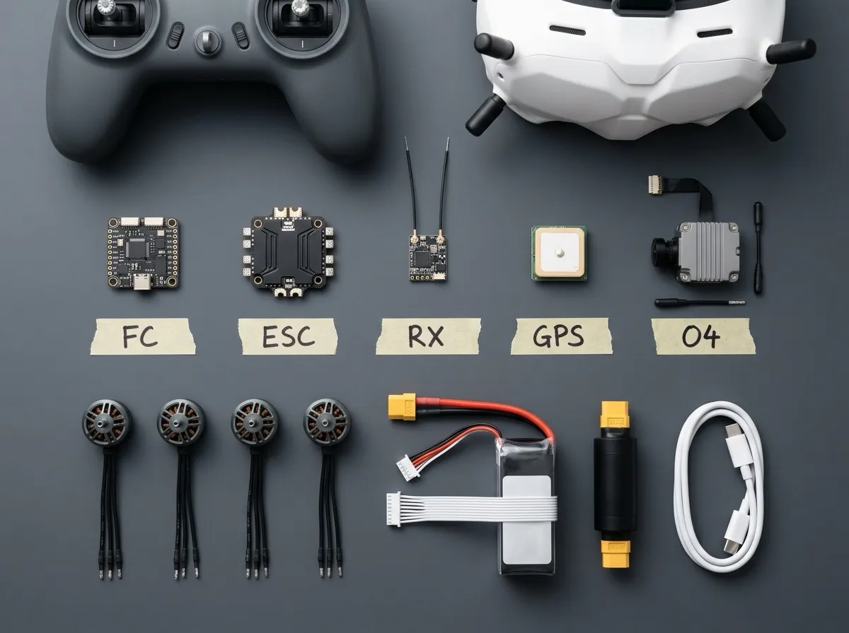 Illustrative render — your actual parts will differ in cosmetic details, but this is everything on the bench before Stage 1.
- (1A) Set up the two configuration tools. The Betaflight App no longer needs installing — it runs in the browser at app.betaflight.com. It requires a Chromium-based desktop browser with WebUSB/WebSerial support (Chrome or Edge — Firefox and Safari won’t work, and per Betaflight’s docs heavily modified browsers like Brave may be unreliable). It’s a PWA, so you can optionally install it from the browser’s address bar for offline use, or use the native Android app instead. ExpressLRS Configurator is still a desktop download (link in the software table above).
- (1B) Bind the receiver to your radio. Flash the RP4TD with ExpressLRS Configurator using the same bind phrase as your existing ELRS gear (a bind phrase is a passphrase that pairs TX and RX automatically). Two hard rules for this fleet: do not change the bind phrase on the Boxer (it would break any existing drone bound to it), and do not upgrade ExpressLRS to 4.0 — it breaks compatibility with 3.x hardware. Stay on 3.3.1, or 3.5.x, which is cross-compatible within 3.x. Success looks like: a solid LED on the RP4TD when the Boxer is powered on.
- (1C) Test the flight controller. Connect the Kakute H7 V2 to your computer over USB-C. It should appear in the Betaflight App (the browser will ask permission to access the USB device); on the Setup tab, the 3D model should rotate when you rotate the board (that’s the gyro working).
- (1D) Test the ESC — with the smoke stopper. Plug the ShortSaver V2 between the LiPo and the ESC for this test (it acts as an electronic fuse: if there’s a short, it cuts power before anything burns). With the FC connected to the ESC by the included 8-pin cable and the battery connected through the smoke stopper: no smoke, no hot smell, and Betaflight shows correct battery voltage (VBAT ≈ 22–25V for a charged 6S).
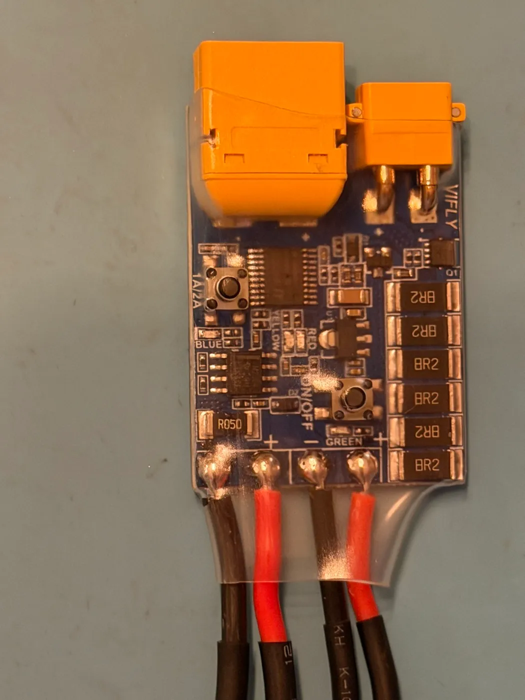 This build’s ShortSaver V2 — battery XT60 into one end, drone XT60 out the other. Note the 1A/2A and ON/OFF buttons and the status LEDs labeled on the board.
5. (1E) Activate the O4 Air Unit Pro. Install DJI Assistant 2 (Consumer Drones Series) — make sure it’s the Consumer Drones Series variant; DJI publishes several differently-scoped Assistant 2 builds, and this is the one that handles the O4 air units. Three O4-specific rules, all from hard experience: never power it without both antennas connected (it can damage the transmitter), activation requires battery power — USB-C alone won’t do it — and it overheats in about 60 seconds on the bench with no airflow, so keep bench sessions short or point a fan at it. Activate it, then confirm live video in the N3 goggles.
6. (1F) Test the GPS. Power the M100 (it can be bench-wired to the FC’s 5V/GND or tested later in-frame) and take it outdoors with a clear sky view. Success: a 3D fix with 6+ satellites. First fix from cold can take several minutes.
This build’s ShortSaver V2 — battery XT60 into one end, drone XT60 out the other. Note the 1A/2A and ON/OFF buttons and the status LEDs labeled on the board.
5. (1E) Activate the O4 Air Unit Pro. Install DJI Assistant 2 (Consumer Drones Series) — make sure it’s the Consumer Drones Series variant; DJI publishes several differently-scoped Assistant 2 builds, and this is the one that handles the O4 air units. Three O4-specific rules, all from hard experience: never power it without both antennas connected (it can damage the transmitter), activation requires battery power — USB-C alone won’t do it — and it overheats in about 60 seconds on the bench with no airflow, so keep bench sessions short or point a fan at it. Activate it, then confirm live video in the N3 goggles.
6. (1F) Test the GPS. Power the M100 (it can be bench-wired to the FC’s 5V/GND or tested later in-frame) and take it outdoors with a clear sky view. Success: a 3D fix with 6+ satellites. First fix from cold can take several minutes.
Stage 2 — Solder the FC/ESC stack, off-frame
Soldering on the bench, before the stack is in the frame, gives you room to work and lets you test joints with a multimeter from every angle.
Parts for this stage
| Part | Qty | Purpose here |
|---|---|---|
| Tekko32 F4 4-in-1 50A ESC | 1 | Receives the battery pigtail and capacitor |
| XT60 pigtail, 10cm 14AWG | 1 | The battery connector — solders to the ESC’s battery pads |
| Filter capacitor (included with the Holybro stack) | 1 | Smooths voltage spikes that damage electronics |
| 8-pin JST-SH cable (included with the stack) | 1 | Connects ESC to FC |
| Kakute H7 V2 FC | 1 | Connected, not soldered, in this stage |
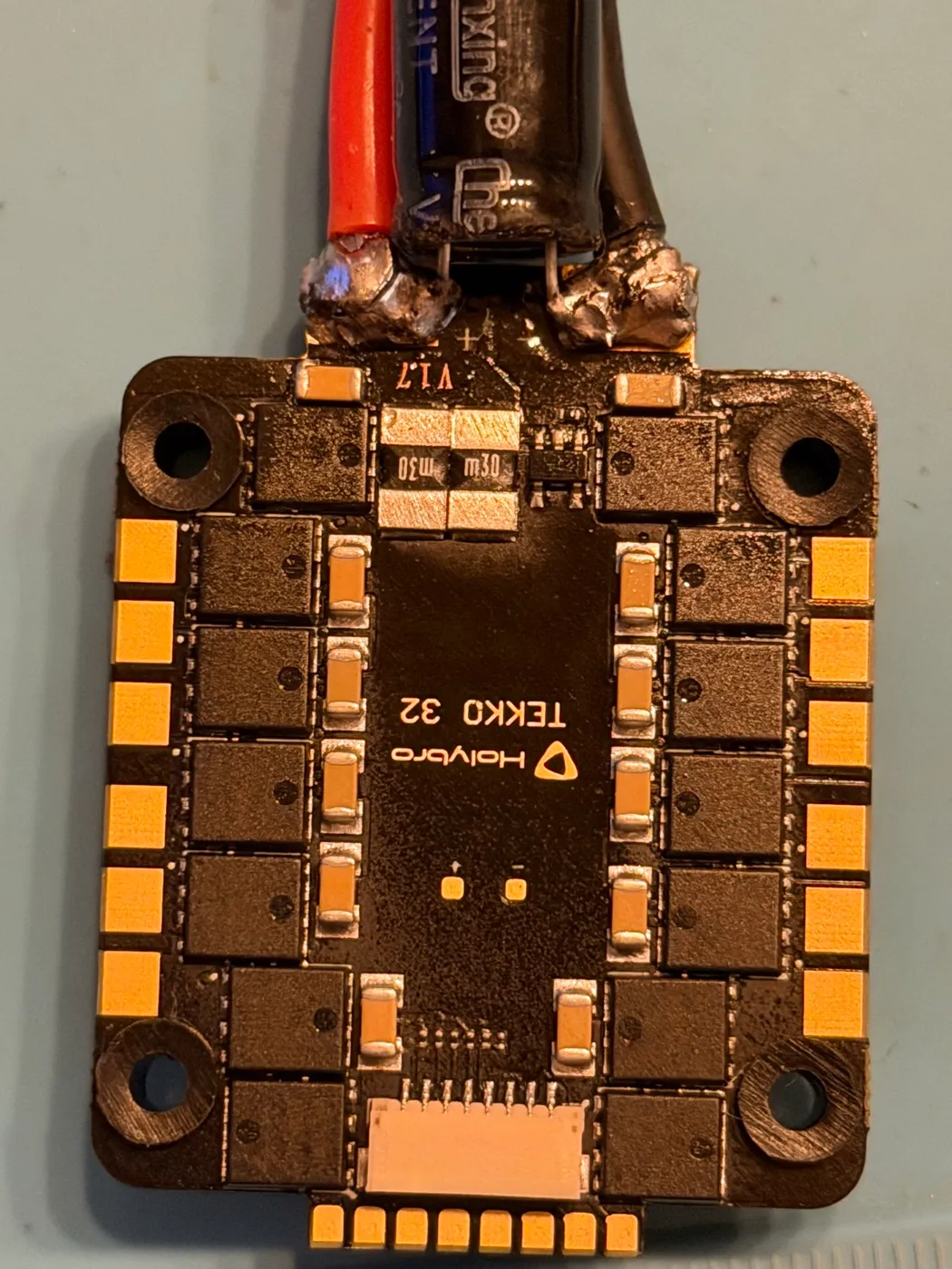 This build’s Tekko32 after soldering — pigtail and capacitor share the B+/B− pads at one edge; the three-pad motor groups at each corner stay empty until Stage 4.
- Identify the ESC’s battery input pads (marked B+ and B− / GND — confirm against the sheet that ships with the Tekko32, or the matching manual on Holybro’s ESC manuals page, rather than assuming their position).
- Tin the pads (melt a small pool of solder onto each) and tin the stripped ends of the XT60 pigtail wires.
- Solder the pigtail: red wire to B+, black wire to B−. Triple-check polarity against the XT60 connector itself before you touch iron to pad — reversed battery polarity destroys the ESC instantly. A 14AWG joint needs real heat; hold the iron until the solder flows smooth and shiny.
- Solder the included capacitor across the same battery pads, observing its polarity — the stripe printed on the capacitor body marks the negative leg, which goes to B−. Keep its legs short, and heat-shrink any exposed leg.
- Multimeter check (do not skip): in continuity mode, confirm B+ to B− is not shorted (no beep; a brief capacitor-charging chirp that stops is normal), and confirm continuity from the XT60’s pins to their pads.
- Connect the 8-pin JST-SH cable from the ESC’s Port 1 to the FC’s ESC port. Per Holybro’s pinout this one cable carries battery voltage to the FC, ESC telemetry (on UART7), ground, the current sensor signal, and all four motor signals M1–M4. (Port 2 exists for 8-motor builds only — leave it empty.)
- First power-up through the ShortSaver V2 smoke stopper (skip if you already did Stage 1D): steady light, no heat, correct voltage in Betaflight.
Don’t bolt the two boards together yet — the stack mounts into the frame in Stage 5, and you may want the boards apart while soldering motor wires in Stage 4.
Stage 3 — Frame: bottom plate, arms, and standoffs
Parts for this stage
| Part | Qty | Notes |
|---|---|---|
| Bottom plate (#1) | 1 | |
| Counter plate (#2) | 1 | Clamps the arms against the bottom plate |
| Front arms (#4) | 2 | |
| Rear arms (#5) | 2 | |
| M3×8 screws (#21) | ×1 | The one standoff point with no arm in the stack — identified by elimination in step 3 (the rest of the #21s go to the top plate in Stage 9) |
| M3×12 screws (#22) / M3×16 screws (#26) | ×4 each | Outer (#22) and inner (#26) arm-root holes — 1 spare of each remains |
| M3×30 screws (#30) | ×4 | Nose column, up through the bottom plate |
| M3×20 standoffs (#19) | ×4 of 5 | Main stack height, onto the inner-arm screws — the 5th has no documented home (see step 5) |
| M3×23 standoffs (#17) | ×2 | Nose stack |
| M3×30 standoffs (#18) | ×3 | Tallest, nose/front |
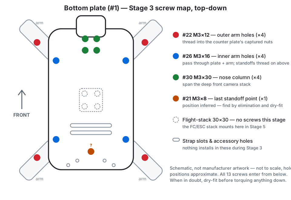 Screw map for this stage — a schematic I drew, not manufacturer artwork, so positions are approximate. Where it matters, the official exploded view below is the authority.
- Lay the bottom plate (#1) flat.
- Sandwich both front arms (#4) and both rear arms (#5) between the bottom plate (#1) and the counter plate (#2) — those are the only two plates in this joint. Don’t fully tighten yet — leave everything finger-tight so you can square up the arms.
- Fasten the sandwich from underneath. Mind the screw length here:
- Outer arm holes (×4): These screw directly into the captured nuts in the counter plate. They take the M3×12 (#22, ×4) screws.
- Inner arm holes (×4): These pass all the way through the arms and counter plate, and the standoffs thread onto them from above. Because they pass through more layers, they take the longer M3×16 (#26, ×4) screws.
- Nose column (×4): The 4 holes at the very front of the bottom plate take the longest M3×30 (#30, ×4) screws, which span the deep front camera stack.
- The one remaining standoff point (×1): after the eight arm screws and four nose screws above, exactly one screw entering from below is left, and it takes a short M3×8 hex screw (#21, ×1). Find it by elimination, not by position: it’s the one remaining plain Φ3 hole that lines up with a standoff position, toward the rear on the plate’s front-to-back midline — the many other holes at the rear are battery-strap slots, accessory mounts, and weight-saving cutouts, none of which take a screw in this stage. The M3×8 is the right length because no arm sits in the stack there — the screw only has to clear the 3 mm plate. (The #21 callout is hard to trace in the official isometric drawing, so this location is partly inference — dry-fit before torquing: if an M3×8 doesn’t comfortably reach threads in your chosen hole, it’s the wrong hole.)
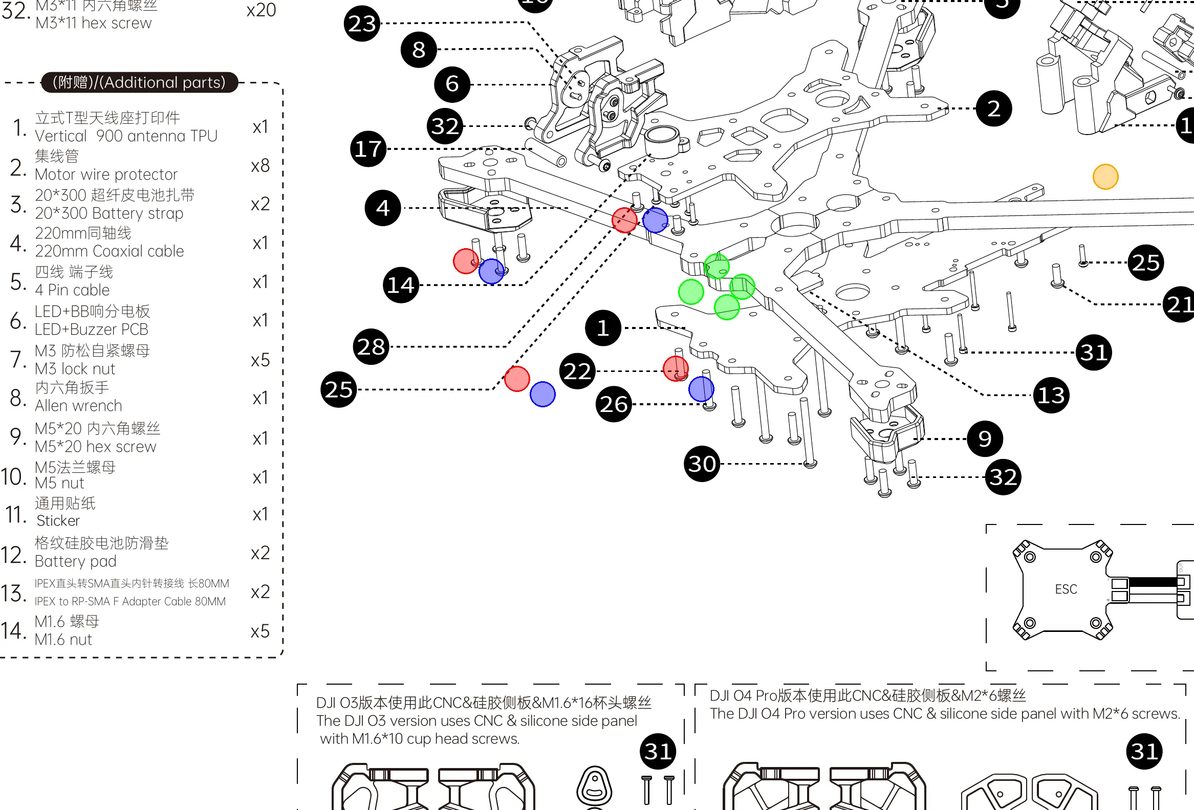 The official exploded-view detail, for cross-reference — Red: outer arm holes (#22). Blue: inner arm holes (#26). Green: nose column (#30). If it and the schematic above ever disagree, trust this one.
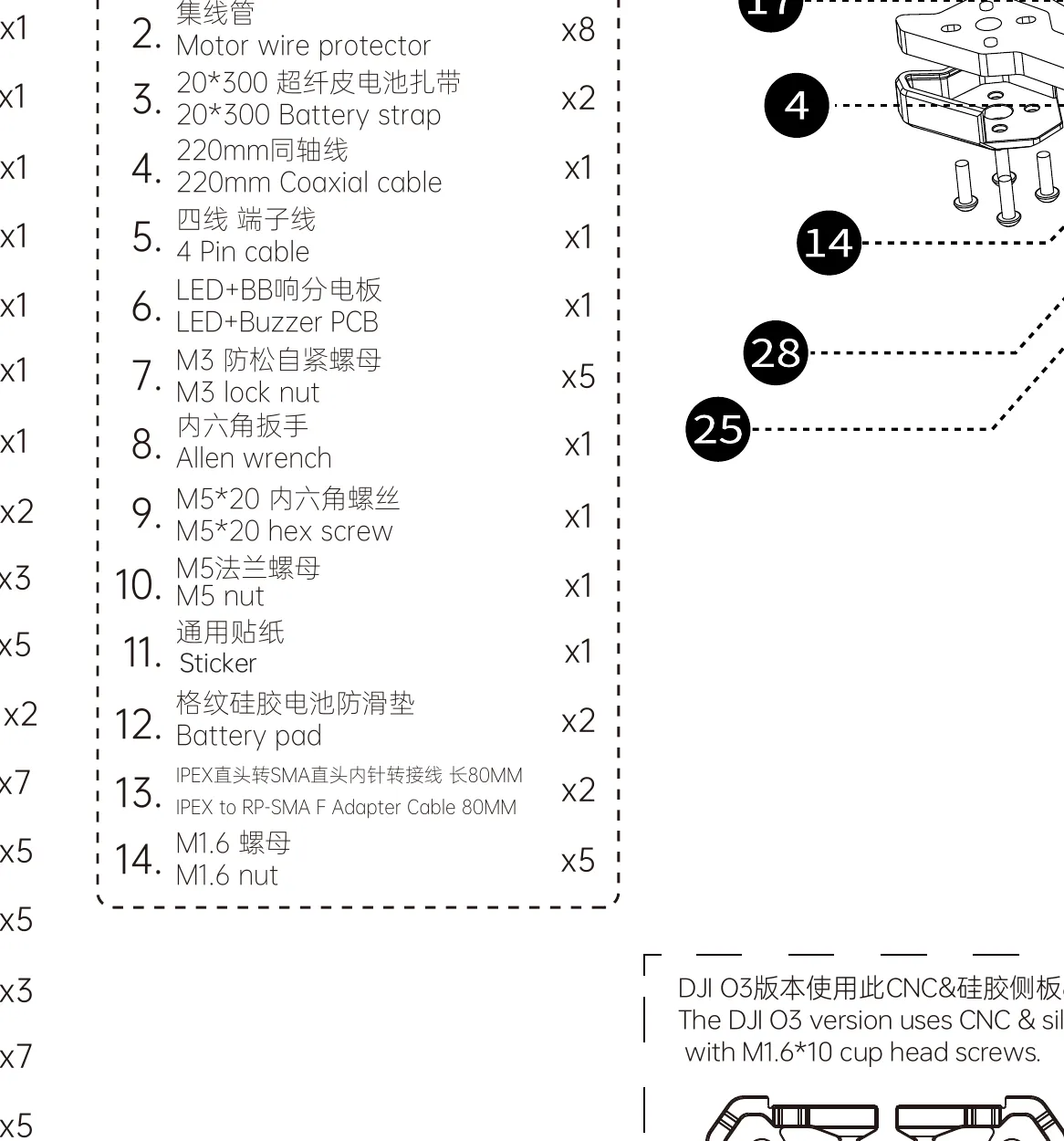 The M5 hardware lives in the additional-parts bag alongside the coaxial cable, battery straps and spares.
- About the M5 hardware in the additional-parts bag. The bag contains one M5×20 hex screw and one M5 flange nut. The official parts list gives them no location, and neither the manual nor iFlight’s product page assigns them a purpose. The arms are rigidly clamped by the M3 hardware you just installed, so set the M5 pair aside as spares — the flange nut matches the motors’ M5 prop-shaft thread, so at minimum it’s a useful spare prop nut. The five M3 lock nuts in the same bag are likewise undocumented general-purpose spares.
- Thread four of the five M3×20 standoffs (#19) onto the inner-arm screws’ protruding threads — the same four points the M3×16 (#26) screws came up through. These form the bulk of your main stack height. The kit’s fifth M3×20 currently has no documented home — it’s the same open question as the single M3×8 in step 3, so set it aside for now.
- Add the M3×23 (#17, ×2) and M3×30 (#18, ×3) standoffs in the nose/camera-stack area — they’re taller because the nose section stacks higher than the rest of the frame. Their exact arrangement isn’t legible in the official exploded view (its #19 callout points into the camera sub-assembly, and the #17/#18 leaders are worse), so treat the map below as approximate and dry-fit against the Stage 6 camera-stack parts before torquing anything.
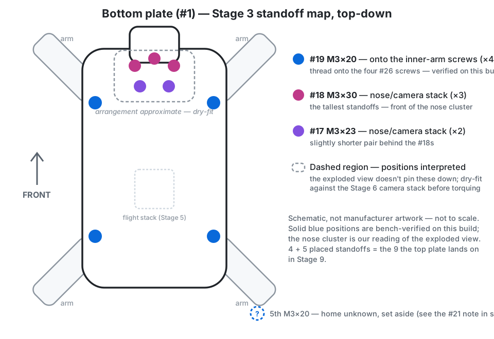 Standoff map — the four inner-arm positions are verified on this build; the nose cluster is our reading of the exploded view. The 4 + 5 placed standoffs are the nine points the top plate lands on in Stage 9.
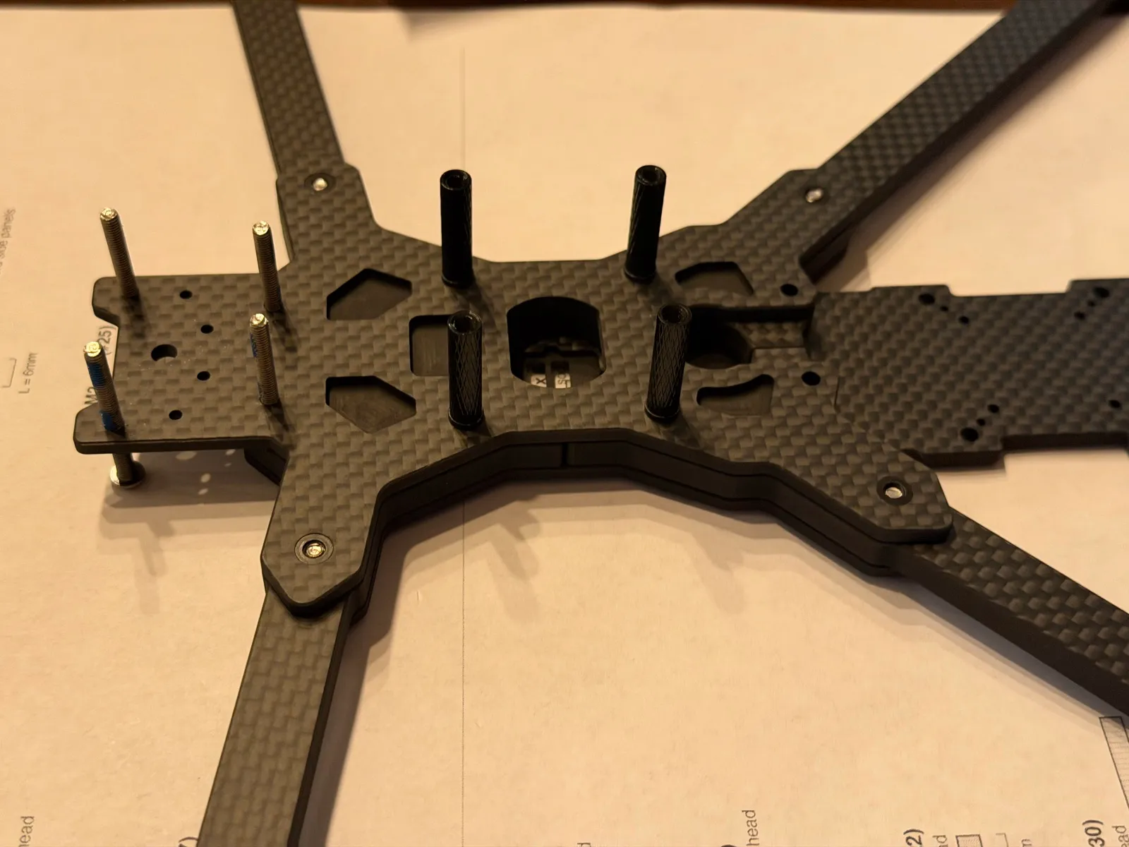 This build’s frame partway through the stage — arm screws in, the four M3×20 standoffs on the inner-arm points, nose M3×30s standing tall.
- Confirm the counter plate (#2) sits raised-boss side up — the face with the raised standoffs around the four centre (flight-stack) holes faces where the top plate will go, and the flat side sits down toward the arms. (The diagram draws it this way and it’s the only orientation that lets the stack mount on the bosses with clearance, but the drawing doesn’t state it outright — set it on both ways for a second and confirm nothing fouls underneath before you screw it down.)
Dry-fit to square the arms. The arms clamp at the very bottom of the frame stack — bottom plate (#1) underneath, counter plate (#2) on top. (You can confirm this on the assembled-frame renders in the manual: the carbon arms sit at the lowest layer, and the structural screws enter from below, up through the bottom plate.) Assemble this joint loosely first so you can square all four arms before torquing the screws down.
Do not install the top plate yet — the earlier frame-only guide put it next, but on a real build it goes on last (Stage 9), after all the wiring underneath it is finished.
Stage 4 — Mount and solder the motors
Parts for this stage
| Part | Qty | Notes |
|---|---|---|
| XING 2806.5 1300KV motors | 4 | 19×19mm M3 bolt pattern |
| M3×11 hex screws (#32) | ×16 of the ×20 | 4 per motor, through arm guard + arm into the motor base |
| Arm guard TPU bumpers (#9) | 4 | Slide on before the motor screws go in |
| Motor wire protectors (additional-parts bag) | 8 | Sleeves over the phase wires |
| Tekko32 ESC (from Stage 2) | 1 | Motor wires solder to its corner pads |
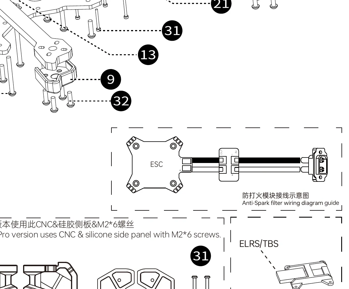 The M3×11 screws (#32) are the largest quantity in the kit (×20) — they cover all four motor mounts plus the arm-mounting points.
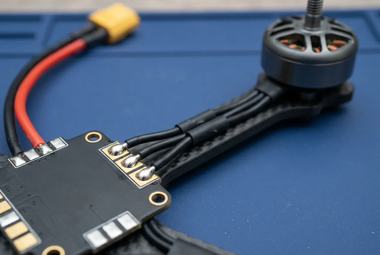 Illustrative render — three identical phase wires per motor, one corner each; confirm the pad layout on the Tekko32’s own sheet.
- Slide an arm guard TPU bumper (#9) onto each arm tip. The motor screws pass through the guard, so it must be on first.
- Seat each motor on its arm tip, aligning the motor base’s 19×19mm holes with the arm’s pattern, and fasten with four M3×11 screws (#32) per motor, screwing up from underneath through guard and arm into the motor base. Snug in a cross pattern. A screw that’s too long will contact the motor windings inside — the M3×11 is the length the parts list assigns to this job, but if a motor feels rough or gritty when spun by hand after tightening, back the screws out and check.
- Feed two motor wire protectors over each motor’s three phase wires (the three identical wires every brushless motor has) as you route the wires along the arm toward the frame center.
- Trim each motor’s phase wires to reach its nearest corner of the ESC with a little slack — measure with the stack held at its Stage 5 position on the center bosses. Cut conservatively; you can’t un-cut.
- Strip, tin, and solder the three phase wires of each motor to the three motor pads on its corner of the ESC (marked M1–M4 zones — confirm pad layout on the Tekko32’s own sheet). Wire order within one motor’s three pads doesn’t matter at this point — motor spin direction is checked and, if needed, reversed in software in Stage 11. (That’s standard practice for 4-in-1 ESCs running DShot, not something in this kit’s docs — the direction check in Stage 11 is what actually confirms it.)
- Tug-test every joint with tweezers and inspect for solder bridges between adjacent pads.
Stage 5 — Mount the stack in the frame
Parts for this stage
| Part | Qty | Notes |
|---|---|---|
| FC + ESC (soldered assembly from Stages 2 & 4) | 1 | |
| Stack mounting hardware included with the Holybro stack (screws/spacers/gummies) | 1 set | The frame kit does not include stack screws — they come with the stack |
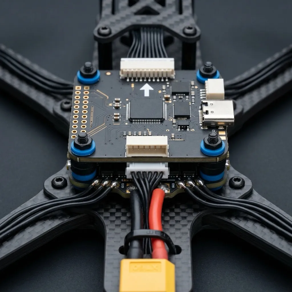 Illustrative render — mount order and gummies per Holybro’s instructions; note the FC arrow pointing at the nose.
- Place the ESC first (it’s the board with the battery pigtail) onto the counter plate’s four raised center bosses — the small raised rings around the plate’s four central Φ3 holes (the 30×30mm flight-stack pattern, which matches the Holybro boards). Not the M3×20 standoffs — those sit farther out at the inner-arm points and carry the top plate in Stage 9. The stack sits low, on the plate itself, inside the ring of standoffs.
- Stack the FC on top, using the spacers/vibration gummies from the Holybro hardware bag between and under the boards as Holybro’s instructions show. Orient the FC so its printed arrow points toward the nose of the frame (if you mount it any other way, you must tell Betaflight the offset in Stage 11 — simplest is arrow-forward).
- Fasten the stack down with the Holybro-supplied hardware. Snug, not crushing — the gummies are supposed to stay soft to absorb vibration.
- Route the XT60 battery pigtail toward the rear of the frame where the battery will sit, and the 8-pin FC↔ESC cable neatly between the boards. Zip-tie the pigtail to the frame so a battery yank pulls on the frame, not on your solder joints.
Stage 6 — Video system: camera stack and air unit wiring
The busiest part of the diagram — six-plus leader lines cross in the nose section, so trace each callout carefully.
Parts for this stage
| Part | Qty | Notes |
|---|---|---|
| DJI O4 Air Unit Pro (camera + air unit body) | 1 | |
| 220mm O4 MIPI coaxial cable (frame kit) | 1 | Replaces the O4’s short stock coax |
| 4-pin cable (frame kit) | 1 | Runs alongside the coax to the FC area |
| GoPro bottom stand TPU (#7) | 1 | |
| CNC camera side plates (#6) | 2 | |
| Dual-hole silicone camera side plates (#8) | 2 | |
| M2×5 hex screws (#23) | ×5 | Camera into side plates (thin material) |
| M2×6 hex screws (#31) | ×5 | O4-specific side-panel screws — not the M1.6s |
| Side panels with LED (#16) | 1 set | |
| M3×6 (#28) / M3×8 (#21) | as shown | Side-panel/stack points |
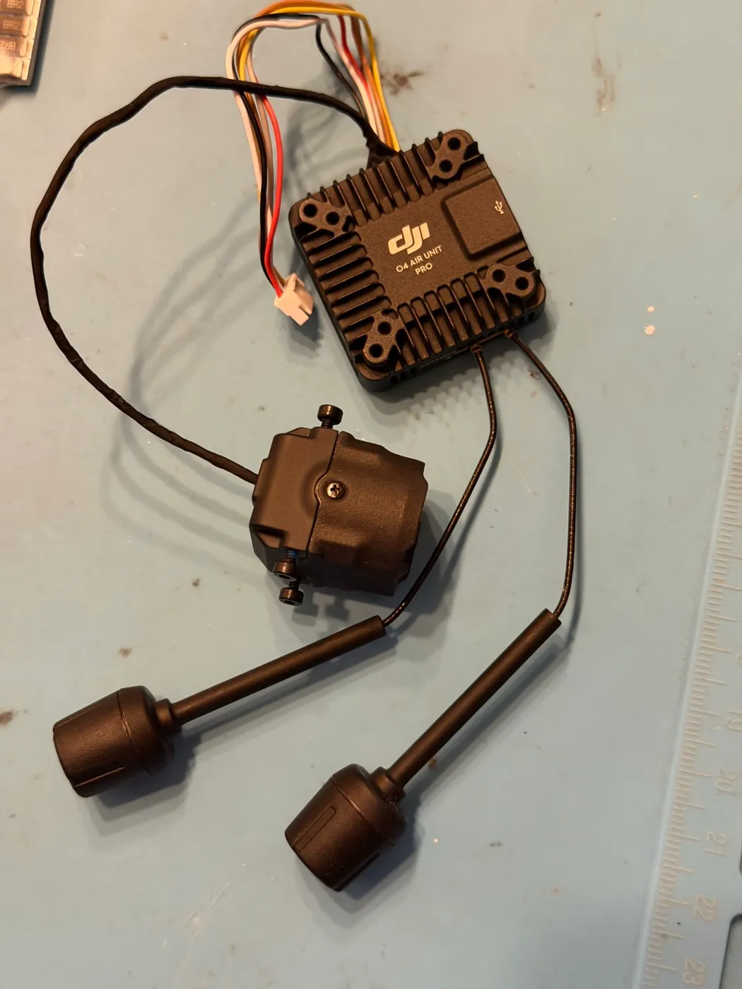 This build’s O4 Air Unit Pro kit — air unit, camera on its coax, and both antennas. Per Stage 1’s warning: never power it with antennas disconnected.
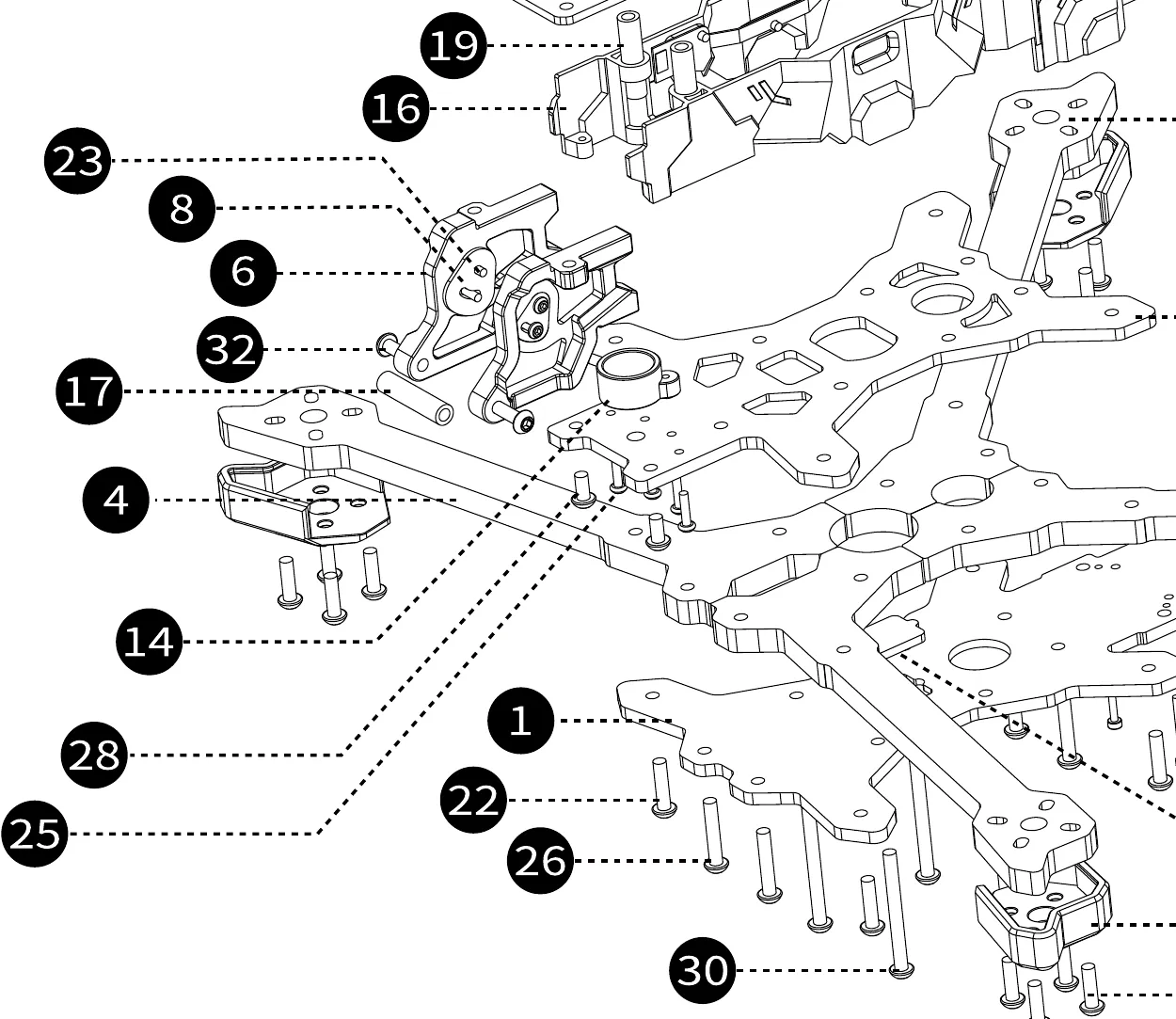 Official exploded-view detail of the nose stack.
6a — Swap the O4’s coax for the long one
The O4 ships with a short camera coax; the frame kit’s 220mm MIPI coax spans the Chimera7’s nose-to-center distance. Per iFlight’s official O4 installation video:
- Remove the two Phillips screws on the O4 camera and separate the lens from its back cover — gently, don’t pull hard.
- Remove the four screws on top of the air unit body and open its top cover.
- Swap the short coax for the 220mm cable at both ends. Before connecting the new coax to the camera, thread it through the lens back cover first — it can’t pass through after it’s connected.
- Seat both connectors firmly, close both covers, and re-fit the screws. Handle coax connectors straight-on; they’re fragile.
6b — Build the camera stack
- Mount the GoPro bottom stand TPU (#7) to the front of the stack.
- Fit the silicone damper balls into the CNC side plates. Per iFlight’s video: raised side facing inward, and they’re handed — L is the left side, R the right. Check the camera’s orientation before committing: the camera logo at the bottom marks the front.
- Attach the camera to the CNC camera side plates (#6, ×2) and dual-hole silicone camera side plates (#8, ×2) using the M2×5 screws (#23) where the plate seats against thin material, and the M2×6 screws (#31) for the O4 side panels — this is the screw the “read this first” warning is about.
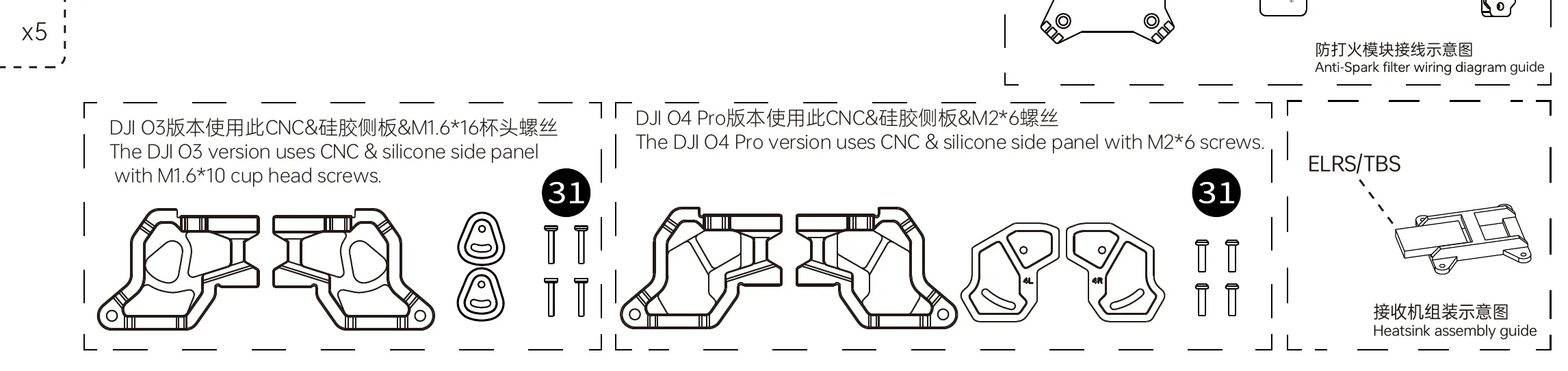 The O3 (left) and O4 Pro (right) side-panel sets from the manual. This build is O4 — M2×6 screws (#31).
- Mount the air unit body on the frame’s VTX plate. The O4 Pro’s bolt pattern is 20mm (inner) / 25mm (outer); the frame offers 20/25/30mm — iFlight’s video uses the 20mm holes with M2×6 screws.
- Install the pre-assembled side panels with LED (#16) onto the frame’s center body at the front, using the general M3×6 (#28) or M3×8 (#21) hardware as shown at that connection point — these panels seat against the frame and are secured by the surrounding stack screws rather than dedicated fasteners. Make sure no cable is pinched as they close.
6c — Wire the air unit to the flight controller
The one wiring change that matters on this build: the Kakute’s 6-pin VTX plug feeds the O4 from the FC’s 9V regulator (the Vtx+ pin), and the O4 Pro’s peak draw can exceed what that regulator supplies. So the O4’s power comes directly from battery voltage (VBAT) instead — the O4 Pro accepts 7.4–26.4V, and 6S (~22.2V) is comfortably in spec.
- Connect the O4’s 6-pin cable to the FC’s VTX port. Per the Holybro pinout that plug carries:
Vtx+,GND,T1(UART1 TX),R1(UART1 RX),GND,R6(an SBUS input — unused here, since control comes over ExpressLRS). - Move the power feed to VBAT: instead of powering the O4 from the plug’s
Vtx+pin, solder the O4’s power wire to a VBAT pad (battery positive) on the FC, with its ground on an adjacent ground pad. Signal wires (T1/R1) stay in the plug. - Route the 220mm coax and the 4-pin cable from the nose back along the frame’s center channel to the air unit/FC area — flat, untwisted, and clear of anything that pinches when the top plate goes on.
Stage 7 — Wire the receiver and GPS
Both devices connect the same way: power (5V), ground, and a two-wire serial connection to one of the FC’s UARTs. The Kakute H7 V2 exposes solder pads for UART3 (R3/T3) and UART4 (R4/T4) — the other UARTs are spoken for (UART1 carries the O4, UART7 the ESC telemetry, UART2 is the FC’s internal Bluetooth, and UART6’s receive pin lives inside the plug the O4 occupies).
This build’s assignment: receiver on UART3, GPS on UART4. The two are electrically identical — if you wire them swapped, nothing breaks as long as your Betaflight port settings (Stage 11) match what you actually did.
Parts for this stage
| Part | Qty | Notes |
|---|---|---|
| RadioMaster RP4TD receiver | 1 | 4 pads, labeled on the board: RX, TX, + (5V), − (GND) |
| HGLRC Mini M100 GPS | 1 | 4 wires: VCC (5V), GND, TX, RX |
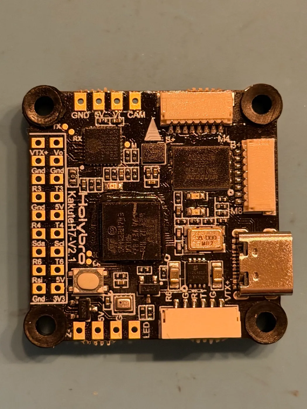 This build’s Kakute H7 V2 (board silkscreen reads V2.1) — R3/T3 and R4/T4 live in the paired pad column along one edge, with Gnd/5V pads between them. Receiver to R3/T3, GPS to R4/T4, each with a 5V and Gnd, signal wires crossed.
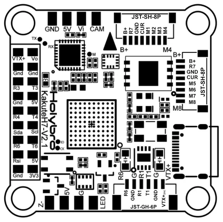 Holybro’s official pinout diagram, mirrored from their documentation — the authority if anything above disagrees with your board. Note it also names the 8-pin ESC connector pins (B+, R7 telemetry, GND, CUR, M1–M4) and the 6-pin VTX plug used in Stage 6.
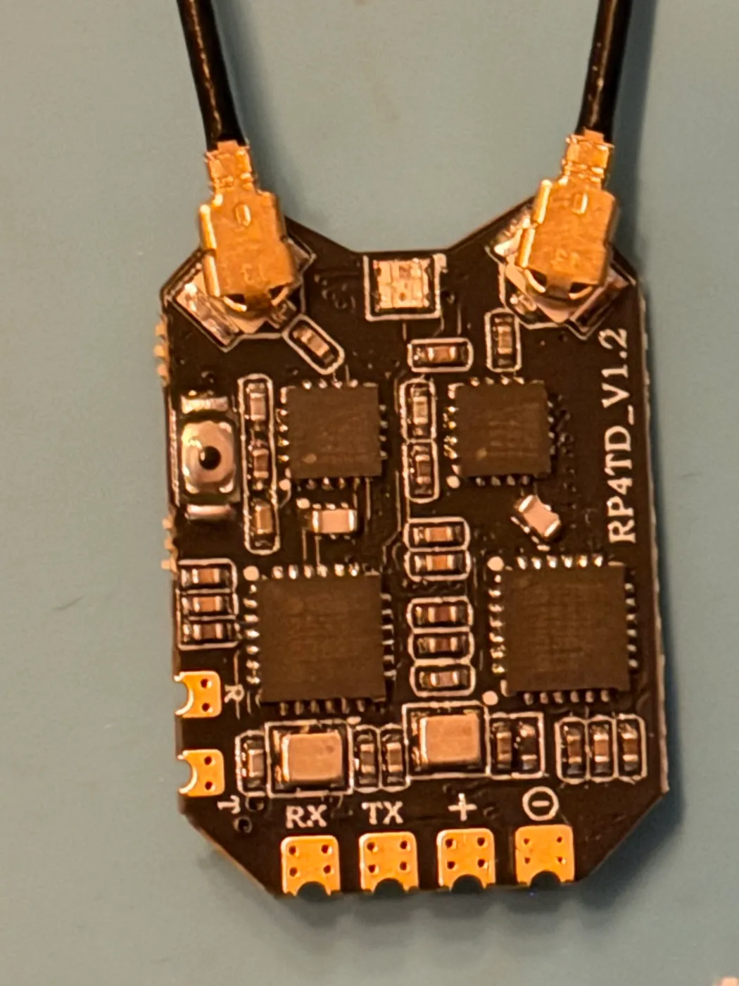 The receiver side of the same wiring (board silkscreen reads RP4TD_V1.2) — its pads are labeled RX, TX, + and −. The + goes to the FC’s 5V (the RP4TD accepts DC 4.5–12.4V per its manual), − to Gnd, and the signals cross: RP4TD TX → FC R3, RP4TD RX → FC T3. Full details in RadioMaster’s manual (mirrored; original).
- Cut all wires to length first by holding each device at its final mounting position (receiver at the rear per Stage 8; GPS on its TPU mount, as far from the VTX antennas as the frame allows — VTX transmissions interfere with GPS reception).
- Wire the receiver to UART3: RP4TD
5V → 5V pad,GND → GND, and cross the signal wires — the receiver’sTX → R3(FC receive), receiver’sRX → T3(FC transmit). Crossing trips up every first-time builder: one device’s transmit must go to the other’s receive. - Wire the GPS to UART4:
VCC → 5V pad,GND → GND, GPSTX → R4, GPSRX → T4— crossed, same as above. - Power budget sanity note: the Kakute’s 5V pads supply 1.5A max (per Holybro); the receiver and GPS together draw a small fraction of that. Don’t hang additional accessories off 5V without adding up their draw.
- Tug-test the joints, then power the FC from USB and confirm no magic smoke and that both devices’ LEDs light.
Stage 8 — Mount antennas, GPS, receiver, and buzzer
All TPU printed parts — the self-tapping screws bite directly into the plastic, no nuts needed.
Parts for this stage
| Part | Qty | Notes |
|---|---|---|
| GPS mount TPU (#11) | 1 | |
| Antenna mount TPU (#10) | 1 | |
| Receiver mount TPU (#12) | 1 | |
| Buzzer holder TPU (#14) | 1 | |
| LED logo TPU (#13) + vertical 900 antenna TPU (additional-parts bag) | 1 each | |
| M2×25 aluminum standoffs (#20) | ×2 | Risers for GPS/antenna mounts |
| M2×8 wash-head screws (#24) | ×3 | Caps on TPU — wide head prevents pull-through |
| M2×8 self-tapping screws (#25) | ×7 | Bite directly into TPU |
| M2×12 self-tapping screws (#27) | ×3 | Deeper bite into thick TPU |
| IPEX-to-RP-SMA antenna pigtails (frame kit) | 2 | |
| VIFLY Finder 2 buzzer | 1 |
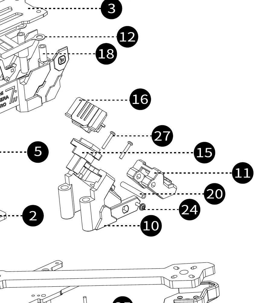 Official exploded-view detail of the TPU mounts.
- Attach the GPS mount TPU (#11) and antenna mount TPU (#10) using the M2×25 aluminum standoffs (#20, ×2) as risers, then cap with M2×8 wash-head screws (#24, ×3).
- Attach the receiver mount TPU (#12) and buzzer holder (#14) using M2×8 self-tapping screws (#25) — these bite directly into the TPU, no nut required.
- Mount the LED logo TPU (#13) and the vertical 900 antenna TPU (from the additional-parts bag) with M2×12 self-tapping screws (#27, ×3) where a deeper bite is needed.
- Seat the M100 GPS on its mount (Velcro or the mount’s own retention), keeping it as far from the VTX antennas as possible, with its ceramic antenna facing the sky.
- Connect the two IPEX-to-RP-SMA pigtails to the O4’s antenna ports (IPEX is the tiny snap-on connector; press straight down until it clicks) and bolt the RP-SMA ends into the antenna TPU mounts. Then attach the O4’s antennas. From here on, never plug in a battery unless these antennas are attached.
- Fit the RP4TD on its mount with its two antennas at roughly 90° to each other (that’s the point of a diversity receiver — two antennas at different orientations so at least one always has signal).
- Fit the VIFLY Finder 2 in the buzzer holder (#14). It’s a self-contained lost-model beeper with its own backup battery; wire it following VIFLY’s included instructions — the Kakute’s buzzer pads are 5V and the Z− (piezo negative) pad per Holybro’s pinout.
Stage 9 — Top plate and battery hardware
Everything under the hood is done — close it up.
Parts for this stage
| Part | Qty | Notes |
|---|---|---|
| Top plate (#3) | 1 | |
| M3×8 wash-head screws (#29) | ×4 | Front holes (TPU GoPro mount) |
| M3×8 hex screws (#21) | ×5 | The 4 middle flight-stack holes and the 1 rear centre hole |
| Anti-slip battery pads (frame kit) | 2 | |
| Battery straps (frame kit) | 2 |
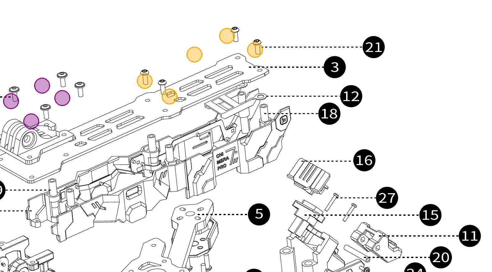 Top-plate fasteners on the exploded view — Purple: front wash-head screws (#29). Orange: middle & rear hex screws (#21).
- Do a final visual pass under the top plate: no pinched wires, coax lying flat, every connector seated.
- Set the top plate (#3) on top. It connects to the 9 vertical standoffs.
- Secure the 4 front holes (which hold the TPU GoPro mount) with the M3×8 wash-head screws (#29, ×4) — the wide cap head prevents the screw from pulling through the flexible TPU material.
- Secure the remaining 5 holes (the 4 middle flight-stack holes and the 1 rear centre hole) with the regular M3×8 hex screws (#21, ×5).
- (Note: the M3×12, M3×16, and M3×30 screws are used entirely on the bottom plate in Stage 3. The kit gives you 5 of each M3×12 and M3×16, leaving exactly 1 of each as a spare after assembling the 8 arm root points. Do not use them on the top plate!)
- Apply the anti-slip battery pads (×2) to the top and/or bottom plate where the battery sits, and thread the battery straps (×2) through their slots.
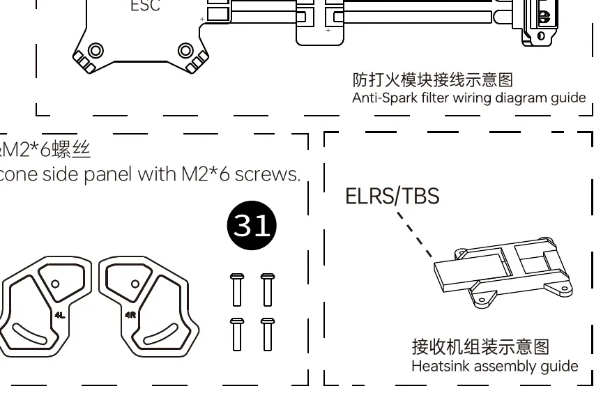 The frame kit’s wiring accessories — by this stage, all of them are installed.
Stage 10 — Full bench test
Parts for this stage: the finished drone, one charged 6S LiPo, the ShortSaver V2 smoke stopper, the Boxer, the N3 goggles, and your computer. No props. Props stay in the bag until Stage 12.
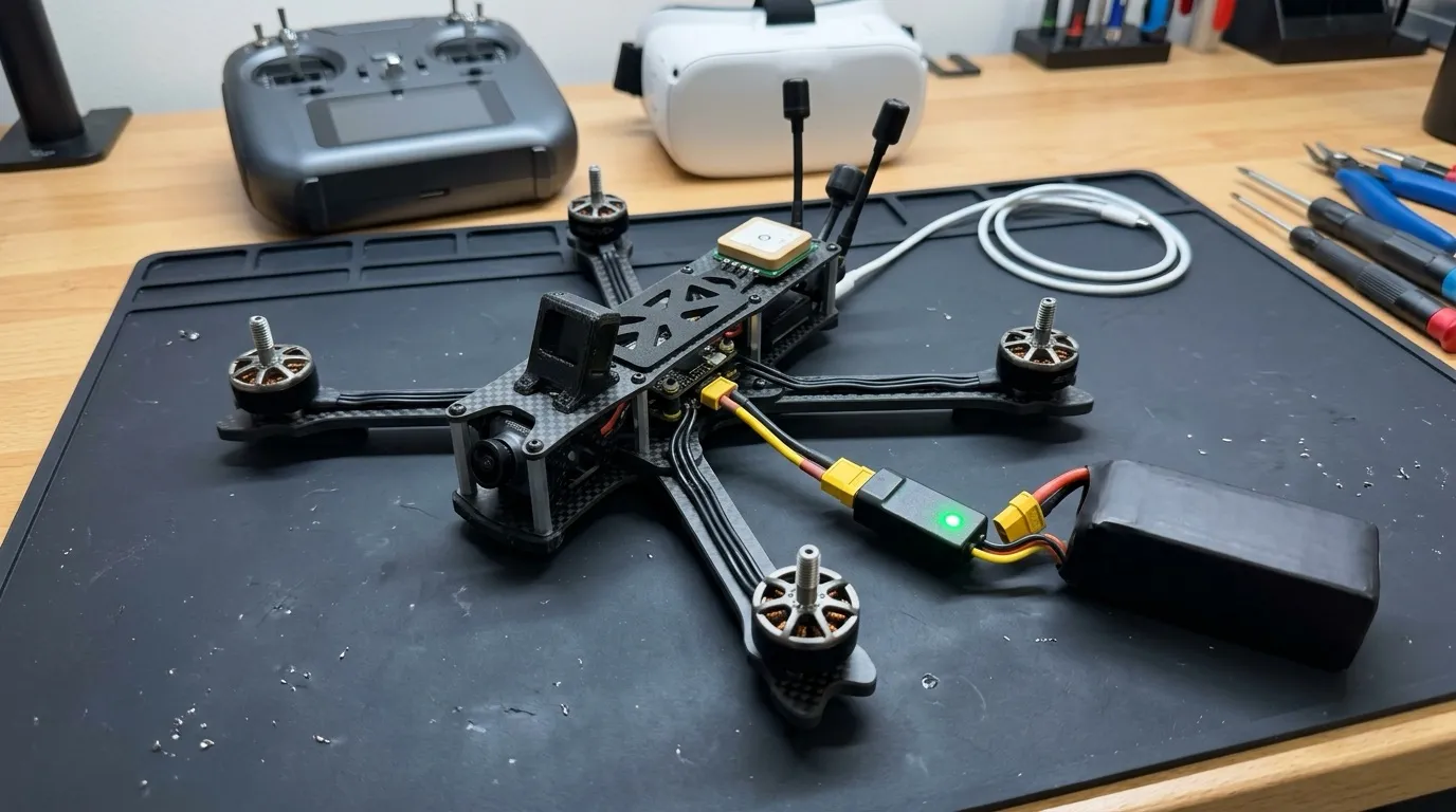 Illustrative render — the chain that matters: battery → smoke stopper → drone, and no props anywhere near the bench.
- Antennas on (both VTX antennas and receiver antennas). Battery in through the smoke stopper. Watch and sniff for ten seconds — steady light on the ShortSaver means no short.
- Confirm in the goggles: live video from the O4.
- Confirm on the radio: link is up (the RP4TD LED solid; the Boxer shows telemetry such as receiver voltage).
- Connect USB, open Betaflight: correct battery voltage on the Setup tab, and the model on screen tracks when you tilt the drone.
- Take it outside (or near a window, patience permitting): GPS gets a 3D fix with 6+ satellites.
- Remove the smoke stopper only after a full pass with zero anomalies; subsequent plug-ins can be direct.
Stage 11 — Betaflight configuration
Software, no tools. Drone connected over USB-C; battery in (through the smoke stopper if anything was reworked), props off.
Settings for this exact BOM (from the build’s BOM verification doc):
| Setting | Value | Where |
|---|---|---|
| Receiver protocol | CRSF (the ExpressLRS serial protocol) | Receiver tab |
| Receiver port | UART3 | Ports tab — set “Serial RX” on UART3 |
| GPS protocol | UBLOX, on UART4 | Ports tab (sensor: GPS) + GPS feature on |
| VTX / OSD | MSP DisplayPort on UART1 | Ports tab — this is how the DJI HD system draws the on-screen display (OSD — telemetry text overlaid on your video) |
| ESC protocol | DSHOT600 (a digital motor signal — no calibration needed) | Configuration tab |
| Failsafe | GPS Rescue | Failsafe tab — configure return-to-home if the control link drops; on a long-range build this is the single most important setting |
- Set everything in the table, saving per tab.
- Modes tab: map an arm switch (a switch on the Boxer that must be flipped to spin motors — non-negotiable safety), plus switches for GPS Rescue and buzzer beeper.
- Motor direction check (props off): on the Motors tab, acknowledge the safety prompt and spin each motor at low throttle. Verify each motor’s position matches Betaflight’s motor map, and each spins the direction the diagram shows. Reverse any wrong-direction motor in software (via the ESC configurator or Betaflight’s motor-direction tools) — this is the software fix that step 5 of Stage 4 promised, and why phase-wire order didn’t matter.
- Confirm the OSD shows in the goggles: battery voltage, GPS satellite count, link quality.
- Radio firmware housekeeping, per this build’s fleet rules: TX and RX both on ELRS 3.3.1 (or matched 3.5.x) — not 4.0.
Stage 12 — Props on and first flights
Parts for this stage
| Part | Qty | Notes |
|---|---|---|
| HQProp 7×3.5×3 V1S props | 4 (of 8) | 5mm bore |
| M5 prop nuts | 4 | On the motor shafts, included with the motors |
- Props go on only now, outdoors, away from people. Each prop is directional: match each prop’s rotation marking to its motor’s spin direction confirmed in Stage 11 (props are made in clockwise and counter-clockwise versions; a prop on a motor spinning the wrong way for it produces thrust downward).
- Seat each prop flush on the shaft and tighten the M5 prop nut firmly against it.
- Preflight: battery secure under both straps · antennas attached · arm switch off · GPS 3D fix acquired before takeoff (GPS Rescue can’t work without a home point) · goggles video clean.
- First hover: arm at low throttle, lift to ~1m, hover, land. Check for vibration/oscillation in the video and listen for anything rough.
- Progress gradually: short line-of-sight passes, then longer flights as trust builds. Watch battery voltage in the OSD — land by ~3.5V per cell (about 21.0V for 6S) under load.
- After the first flight: check motor temperature (warm is fine, too-hot-to-touch is not), re-tighten prop nuts, look over every screw.
Notes on ambiguous hardware
A few of the mid-length M3 screws (#22 M3×12, #26 M3×16, #21 M3×8, #30 M3×30) look nearly identical once out of the bag and are only distinguishable by careful measurement — sort them into labeled containers before you start, since the diagram’s callout lines get genuinely hard to trace at the stack’s busiest points (the nose, where 6+ leader lines cross).
To make sorting painless, print the screw size gauge (PDF) at 100% scale (no “fit to page” — that will shrink it and throw off the measurements). Lay each screw over the outlines to read off its size and item number before you commit it to a stack point.
A note on part names, order, and certainty
The only frame parts and item numbers used here are the ones iFlight’s official parts list actually names (bottom plate #1, counter plate #2, top plate #3, arms #4/#5, and so on) — no invented names. The item numbers, screw sizes, and pinouts are authoritative; the build order and any description of how parts physically stack are interpretation — of an isometric drawing, of iFlight’s O4 upgrade video, and of standard build practice, each flagged as such where it appears. Where a fastener’s exact location matters, trust the numbered callouts in iFlight’s diagram over my prose, and dry-fit before you torque anything down.
Sources: iFlight exploded-view parts list (LR18005-…-250224.pdf, mirrored here) · iFlight O3→O4 upgrade video · Holybro Kakute H7 V2 pinout · this build’s BOM & compatibility-verification document.